 CADRE Flow 3
Hydraulic and pipe flow system software
Formulated by the finite element method
New version 3.2
CADRE Flow provides for calculating
- Flow rates, pressures, losses, and velocity
- Hydraulic grade lines, energy lines
- Power available, required, and lost
- Forces on joints and fittings
- Joint and fitting losses
- Pump requirements
- Turbine requirements, unit discharge
- Cavitation detection and evaluation
- Vary viscosity, temperature, and vapor pressure within the system
- Unrestricted variations of the Reynolds number within the system (laminar, turbulent, transition)
- Unlimited complex 3D networks and piping layouts
- Automatic environmental conditions and fluid setups for common fluids in any system of units
- Easily handle low speed flow systems (biofilters)
System requirements
For Windows™ 10, 8.1, 8, 7, Vista (32 & 64 bit), XPDownload
CADRE Flow evaluation (fully functioning software)
Overview
CADRE Flow is a hydraulics engineering application for Windows. It is oriented toward solving for a simple fluid flow medium in a complex system network.
CADRE Flow is developed using the basic principles of finite element method as applied to to a piping system. The emphasis is on handling large complex piping systems at the system wide level but with very simple incompressible fluid flow principles at the finite element level. There is virtually no limit to the degree of complexity (joints, lines, and line segments) that can be constructed and solved. Although limited to incompressible flow in pipes, CADRE Flow can be used to handle some low speed air flow systems such as ventilation ducts where the overall pressure differential is relatively small.
The piping system is the medium that forms the finite element analogy. In CADRE Flow, the elements are considered as pipes and the nodes are connecting points for the pipes or just intermediate points within pipes where information such as pressure, velocity, flow, etc. are desired.
The solution is conducted on a specific defined piping system which may be part of a larger system as long as the information at the defined boundaries are sufficient to solve the model.
The system may contain different properties of temperature, viscosity, and vapor pressure for the fluid in different parts of the system allowing one to investigate the effects of hotter or colder fluids after a heat exchanger.
Flow elements
The basic finite element used in CADRE Flow to construct flow networks are based on a simple straight section of pipe with a constant diameter.
Although the element is based on a simple pipe segment, it can also be a container for specified flow properties (i.e. pumps, turbines, loss fixtures).
The pipe element can be designated as one-way pipes to account for check valves.
The pipe element can be assigned a device such as a pump (input) with a flow rate or a turbine (output) with an energy loss.
 The pipe element can be assigned a device such as a pump
(input) with a flow rate or a turbine (output) with an
energy loss.
The pipe element can be assigned a device such as a pump
(input) with a flow rate or a turbine (output) with an
energy loss.
The pipe element can also be designated as a tank element
which is can represent a reservoir or a flow through filter
tank with the inlet at the top and outlet at the bottom.
Element properties that are typically assigned to the
pipe are
length, diameter, roughness, and discrete loss factors.
Element losses
- pipe friction losses are calculated according to the Darcy equation based on their assigned lengths and roughness or__
- or by discrete (minor) loss factors, or a combination of both factors and friction so that configuration and fitting losses can be included.
In establishing pipe friction, the full range of Reynolds number are considered from laminar, through transition, to turbulent so that a proper friction factor for each element is automatically provided irrespective of the flow velocity in the element.
Shown below is a Schematic 2D model using the tank element, a pump, connection pipes, and a one-way pipes to represent a series of 2 biofilter tanks for water treatment. The a one-way check valve pipe used as an overflow return system in order to limit the flow through the biofilter system to precisely the value desired as determined by the hydraulic conductivity of the filter aggregate.
In this model, when the pump rate exceeds 2.0 m3/hr then the overflow pipe handles the excess. When the pump rate is below 2.0 then the overflow pipe closes and the system flow is equal to the pump flow.
This is one of the many sample models provided with CADRE Flow.
Model styles
The models can be considered schematic (with assigned
lengths for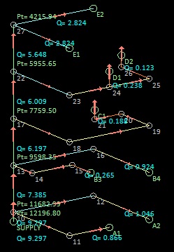 elements) or geometric (with element lengths
determined by the coordinates of the system drawing) or a
combination of both.
elements) or geometric (with element lengths
determined by the coordinates of the system drawing) or a
combination of both.
Likewise, the elevation of nodes (for
gravity effects) can be schematic with assigned elevations
or simply use elevations determined by the coordinates of
the system drawing.
The models can be full 3D representing a complete piping
system for a 3D structure (like the multi-story piping
diagram below) or simple 2D schematics of a flow
system.
The models can be full 3D representing a complete piping
system for a 3D structure (like the multi-story piping
diagram below) or simple 2D schematics of a flow
system.
Likewise, the elevation of nodes (for gravity effects) can be schematic with assigned elevations or simply use elevations determined by the coordinates of the system drawing.
The models can be full 3D representing a complete piping system for a 3D structure (like the multi-story piping diagram below) or simple 2D schematics of a flow system.
Models can be developed_
- From scratch by putting points and elements directly on the screen with the screen editors,
- by starting with the Quick Modeler that generates a basic starting template,
- by importing a text file list of nodal coordinates, then finishing by connecting elements and assigning properties with the pipe element editor,
- by importing a simple model described by a text file,
- by importing a drawing exchange file (dxf) from a CAD application,
- by starting with the Quick Modeler that generates a basic starting template, or
- by importing a text file list of nodal coordinates, then finishing by connecting elements and assigning properties with the pipe element editor.
Single line pumping situations
Develop pump requirements and pipe sizes for typical single line pumping situations, accounting for losses from friction, reentrants, and pipe fittings.
Water distribution systems
CADRE Flow can solve any distribution network (e.g. area water systems, fire suppression sprinkler systems), enabling the determination of supply requirements, piping sizes. The system at the left could be a zonal system for a small town.
Develop load requirements for piping joints
Both pressure and momentum forces can be developed combined or individually.

Simulate low speed air duct systems
Graphical outputs
Plot hydraulic grade lines, energy lines, distributions of pressure head, velocity, flow rate, etc. over any selected path in a fluid flow network.
Turbines and pumps
Output for turbines are total power available, net effective head, and unit discharge.
Heat exchangers
Vary the fluid temperature, viscosity, and vapor pressure within the system to account for heating and cooling elements.
Water treatment systems
3D model of a large biofilter array for a water treatment plant. One of the many detailed tutorial exercises provided in the Help tutorial illustrating complete construction, setup, solution and commentary.
Output
The output can be displayed in tables or directly on a schematic of the model. The numeric format, font, and color of the data, as well as the type of data, can be displayed on the model. Below is a 5 outlet flow system.
This is a typical display of the full system solved with line flow and nodal total pressure displayed.
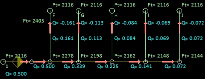
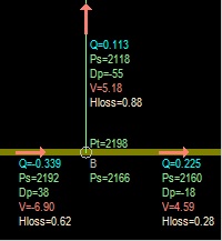
And below, an expanded view choosing to display more data in lines around joint B.
Capability
CADRE Flow has virtually unlimited nodal and element capacity. Limits result from the allocation of memory by your computer and operating system.
Help and documentation
The context sensitive help system provides an overview of the flow analysis methods, help for using CADRE Flow and help in getting started with 11 step-by-step practice exercises. An extensive User Manual is also provided in an electronic searchable format but also formatted in convenient American and European paper sizes for printing.
Over 25 developed and solved sample models are provided, each with detail descriptions of construction methods and analytical results including comparisons to classical methods. You can download a guide to the sample files which provides an overview of the wide variety of problems you can solve with CADRE Flow.
Administration
License
Three (3) simultaneous installations (seats) allowed on the standard license. All CADRE Analytic granted software licenses are perpetual and there are no maintenance fees.
Technical support
Reasonable technical support on engineering projects by practicing professional engineers is free of charge.
Software support
Support for installation and continued functioning is always free and provided by real people by telephone and by e-mail.
There are no popup ads or other promotional features attached to the evaluation application and you do not need to register your email address in order download and run the evaluation version.