 CADRE Geo
7
CADRE Geo
7
Geodesic design application
System requirements
For Windows™ 10, 8.1, 8, 7, Vista, XPCADRE Geo
CADRE Geo is a serious design tool for architects, engineers, and designers of geodesic and other spherical type structures including geodesic domes.
CADRE Geo is not only a practical design tool but is an educational tool as well. It supports all of the main types of geodesic layouts (breakdown methods) for the icosahedron, octahedron, and tetrahedron for both Class I and II with special features for studying single face layouts.
CADRE Geo is a design utility that can generate a wide variety of geodesic and spherical (or ellipsoidal) 3D (wire frame and surface models) for import to CAD or to finite element analysis applications.
Model types
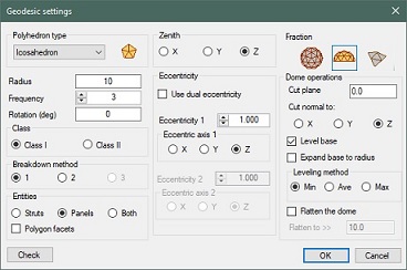
The 'Geodesic' feature can produce Icosahedron, octahedron, and tetrahedron models of Class I and II of virtually any frequency with three different types of breakdown. Facets can be triangles or polygons.
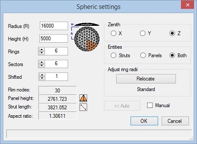
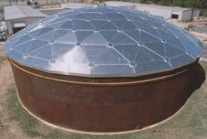
CADRE Geo has a special modeling feature called the 'Spheric' that can be used for designing large low profile storage tank covers. This feature is frequently employed in industries (e.g. petroleum industry) involved with the design of tank top roofs constructed of steel or aluminum sheet panels.
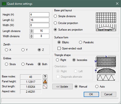
CADRE Geo has a modeling feature called the 'Quad dome" that can be used for designing dome shapes (elliptical or parabolic surface) on a rectangular base. This feature is employed in the design of rectangular tank covers and skylights.
In addition to generating its own structural types, CADRE Geo can import Custom text files of spherical points and elements created in other applications to take advantage of the data analysis and output features provided in CADRE Geo.
Data presentation and output
It can produce tables of hubs, struts, and panels grouped into like types with detail geometric information. The like-types of hubs, panels, and/or struts can be highlighted on the structural display. Design drawings of hubs and panels can be output as clean CAD (DXF) files suitable for import to CAD or to structural analysis applications or fed to machine shop equipment for automatic production.
CADRE Geo is not a cookbook for building geodesic domes nor does it perform, or confirm, the structural integrity of any design. Our structural analysis application, CADRE Pro, is very well suited for structural analysis of complex structures including geodesics with many features provided especially for this purpose.
Geodesic features
Spheres, spheroids, ellipsoids (single and dual eccentricity), domes, or just a single face for breakdown study. Geodesic types include Tetrahedron, Octahedron, Icosahedron of both class I and class II.
Construction components struts-only, panels-only, or both integrated struts and panels. CADRE Geo provides for classification of parts into hubs, panels, and struts of the same type with the ability to highlight like types on the display and generate a drawing of each type or a drawing of every individual item.
Support for the standard breakdown methods (Method 1, Method 2, and Method 3 described by Kenner, "Geodesic math and how to use it".
New version 7.3 allows polygon style facets for all geodesic types.
Geodesic domes
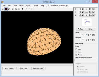
Domes are created by defining a cut plane within the contour of the spherical (or ellipsoidal) structure.
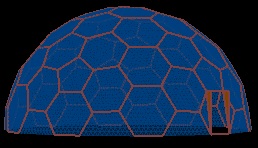
The dome base (cut plane) can be established relative to any Cartesian plane independent of the chosen geodesic construction zenith. Facets can be triangular or polygonal facets such as the polygon greenhouse shown below.
There are specialized dome construction tools for handling truncation lines and leveling bases.
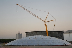
Low profile spherical surfaces
Provisions for creating spherical segment type dome roof tops. These are low profile geodesic structures suitable for small and large storage tank covers.
Outputs for these structures can be detail panel and hub drawings already labeled with dihedrals, angles, bolt hole locations, and other dimensions.
Rectangular based domes
New in version 7 is a feature to generate a wide variety of dome structures over a rectangular base.
These type of structures are often used for skylights and covered structures for industrial ponds.
Output
Tables of detail design data for the structure (e.g. volume, surface area, etc.), struts, hubs, and panels.
Drawings (DXF format) of the structure with identification of hub and strut members (by type or by individual number)
Drawings (DXF format) of panels with dihedrals, vertex angles, and dimensions as well as connection codes.
A complete set of hub or panel drawings can be output all at once.
Dihedral angles can be output as miter angles (for cutting the panel edge) or alternatively as inter-panel angles.
If struts are included in the model, the associated strut type code (S1, S2, etc.) is also shown on each panel edge in the panel drawing.
The structure can be output as a finite element model specifically for use in the CADRE Pro structural analysis application.
There are no pop-up ads or other promotional features attached to this evaluation application and you do not need to register or supply your email address or any other information in order download and run the evaluation version.